What I've Been Doing
The last week I’ve been working on this mechanism that allows us to change the position of our secondary mirror. This amounts to “focusing” our telescope. In the original design it was not clear as to how much temperature changes would cause the foam cone to expand and contract. Well after some difficulties this past year, we have chosen to make our focus adjustable. So the apparatus that is shown in the pictures below is precisely the mechanism to make it so.
I have been working on assembling this piece. It was manufactured in our machine shop in Chicago, I helped some there too but mostly my advisor designed it. The mechanism consists of two metal rings connected in three places with electric stepper motors and steel shafts that run through linear bearings. The shafts provide the rigidity and the linear bearings slide along on the shafts allowing the plates to separate or combine smoothly. The stepper motors provide the motion of the plates and the vertical support. Stepper motors drive a screw that pushes the plates together or apart.
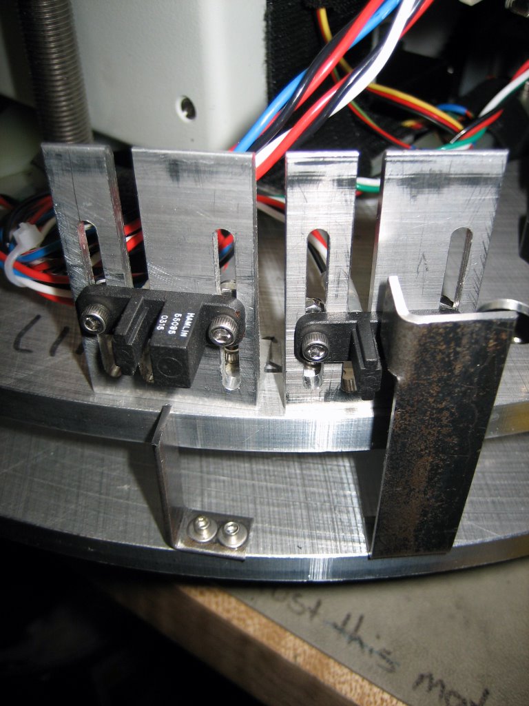
There are also two limit switches on the side of the rings that prevent them from separating too far or slamming together. These are Hall effect probes. They are activated when a magnetic or ferrous material is passed through the two magnets inside the probe. Metal passing through magnets can create currents; in this case a voltage is induced via the Hall effect.
Suspended on and within the rings is a calibration source. This is just a blackbody source of microwave radiation that can be exposed to the detector in a controlled manner. A mirror is flipped in and out of the detector’s line of sight, reflecting this radiation. There is also a polarizing grid that is rotated in front of the blackbody creating a polarized source to test our detector with. Since this apparatus sits atop the foam cone and we cannot send wires back and forth, a small IR transmitter/receiver is used to control the equipment; much like a remote control for your T.V.. Finally, a rechargeable battery that must be replaced a few times a week powers all of the equipment.
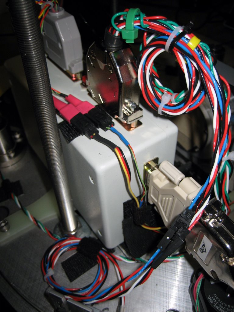
Ok, check out some of the pictures of this thing. I put most of it together from pre-fabricated pieces, designed the limit switch setups and did almost all the wiring from scratch. The wiring was the best part; I hooked up all the little connectors and sub-connectors and fastened everything down neatly.
This is a front side view of the focus mechanism. Front right are a motor and a linear bearing, front left is the IR transmitter, then the polarized grid rotator and behind that the flip mirror then the control box with the circuit board that runs the thing. To the right and a little in front of the control box is the battery.

This is a view of the focus mechanism from the top and the next one is from the back. In the back view, the limit switches are visible at front right.


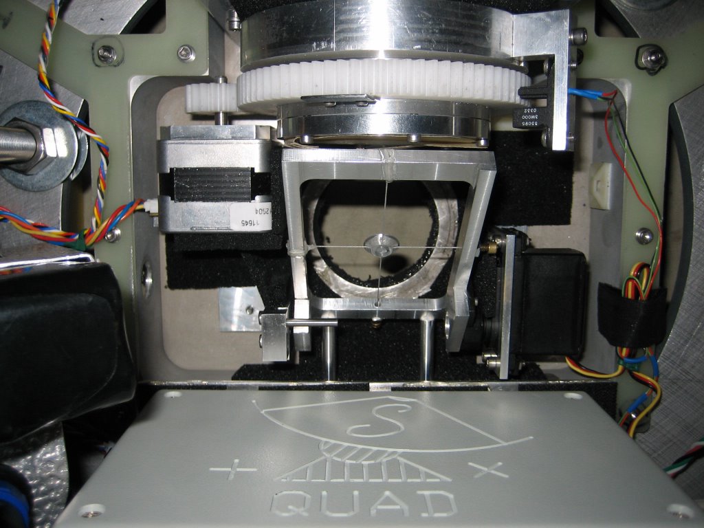
This is a close-up view of the flip mirror. The actual mirror is a small disc suspended by nylon thread inside the metal frame. The next photo is the flip mirror, flipped down into the field of view of the telescope detector (when its in the telescope).


A view of the limit switches; when the black sensors move up or down, the steel pieces slip inside and trip the switch stopping the plate.

Finally, a close-up view of some of the wiring I did to make the whole thing run!

The last piece of info is that the mirror would be mounted on the underside of this mechanism, facing downwards so that the shiny curved side is looking down towards the primary dish below. So that’s the product of some of my labor while I have been down here. Totally boring huh? Actually, its quite satisfying when everything starts to work as planned and designed, but incredibly frustrating otherwise!
I have been working on assembling this piece. It was manufactured in our machine shop in Chicago, I helped some there too but mostly my advisor designed it. The mechanism consists of two metal rings connected in three places with electric stepper motors and steel shafts that run through linear bearings. The shafts provide the rigidity and the linear bearings slide along on the shafts allowing the plates to separate or combine smoothly. The stepper motors provide the motion of the plates and the vertical support. Stepper motors drive a screw that pushes the plates together or apart.
There are also two limit switches on the side of the rings that prevent them from separating too far or slamming together. These are Hall effect probes. They are activated when a magnetic or ferrous material is passed through the two magnets inside the probe. Metal passing through magnets can create currents; in this case a voltage is induced via the Hall effect.
Suspended on and within the rings is a calibration source. This is just a blackbody source of microwave radiation that can be exposed to the detector in a controlled manner. A mirror is flipped in and out of the detector’s line of sight, reflecting this radiation. There is also a polarizing grid that is rotated in front of the blackbody creating a polarized source to test our detector with. Since this apparatus sits atop the foam cone and we cannot send wires back and forth, a small IR transmitter/receiver is used to control the equipment; much like a remote control for your T.V.. Finally, a rechargeable battery that must be replaced a few times a week powers all of the equipment.
Ok, check out some of the pictures of this thing. I put most of it together from pre-fabricated pieces, designed the limit switch setups and did almost all the wiring from scratch. The wiring was the best part; I hooked up all the little connectors and sub-connectors and fastened everything down neatly.
This is a front side view of the focus mechanism. Front right are a motor and a linear bearing, front left is the IR transmitter, then the polarized grid rotator and behind that the flip mirror then the control box with the circuit board that runs the thing. To the right and a little in front of the control box is the battery.
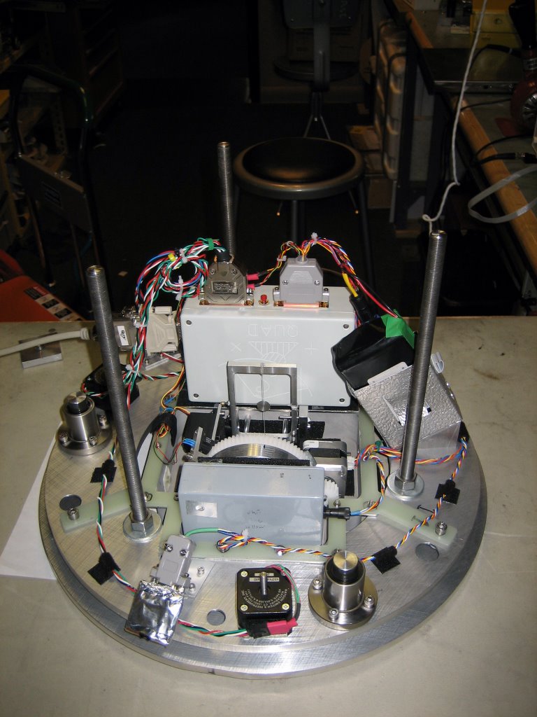
This is a view of the focus mechanism from the top and the next one is from the back. In the back view, the limit switches are visible at front right.


This is a close-up view of the flip mirror. The actual mirror is a small disc suspended by nylon thread inside the metal frame. The next photo is the flip mirror, flipped down into the field of view of the telescope detector (when its in the telescope).

A view of the limit switches; when the black sensors move up or down, the steel pieces slip inside and trip the switch stopping the plate.
Finally, a close-up view of some of the wiring I did to make the whole thing run!
The last piece of info is that the mirror would be mounted on the underside of this mechanism, facing downwards so that the shiny curved side is looking down towards the primary dish below. So that’s the product of some of my labor while I have been down here. Totally boring huh? Actually, its quite satisfying when everything starts to work as planned and designed, but incredibly frustrating otherwise!
posted by Robert B. Friedman at 12:07 PM
![]()
![]()


0 Comments:
Post a Comment
<< Home